Project: Immunity issue of a flow sensor used in automotive application
Timescale: 3 working days
Scope of work:
A hydraulic system flow monitor, originally designed for industrial application, but now for automotive application, has experienced EMI immunity issues, particularly radiated immunity (between 200 and 400 MHz) and BCI failures, the scope of the package of work therefore are:
- Review the hydraulic monitor and identify EMC design areas of improvement.
- Workbench pre-compliance test to reproduce failure modes.
- Modification on the module to prove delta in dB improvement to give sufficient margin to pass EMC test.
The client is an SME company based in both US and the UK.
Note: This project also generates an interesting article which you can find it here in our Technical page.
There’s nothing particularly wrong with the system as it passed industrial EMC standard in the past. However, automotive EMC standards are much more stringent.
The fact that the unit failed only in certain frequency range indicates there might be strong resonance point at those frequency range. Resonance could be caused by PCB structure, a long trace on the PCB, or cable wiring.
The issue was quickly fixed once the weak point(s) in the system were identified.
Interesting lesson learnt from this project was one should never underestimate the complexity of an EMC project. Each project has its own EM characteristics and should always be treated as if you have never worked on similar issue in the past. In this case, the system reminded me of a project in the past, therefore I jumped the gun and started to apply common mode filters in the front-end. The CMC and capacitors that were retrofitted improved the system immunity performance, however, not to a level with good margin. This indicated that the noise coupling path is somewhere else.
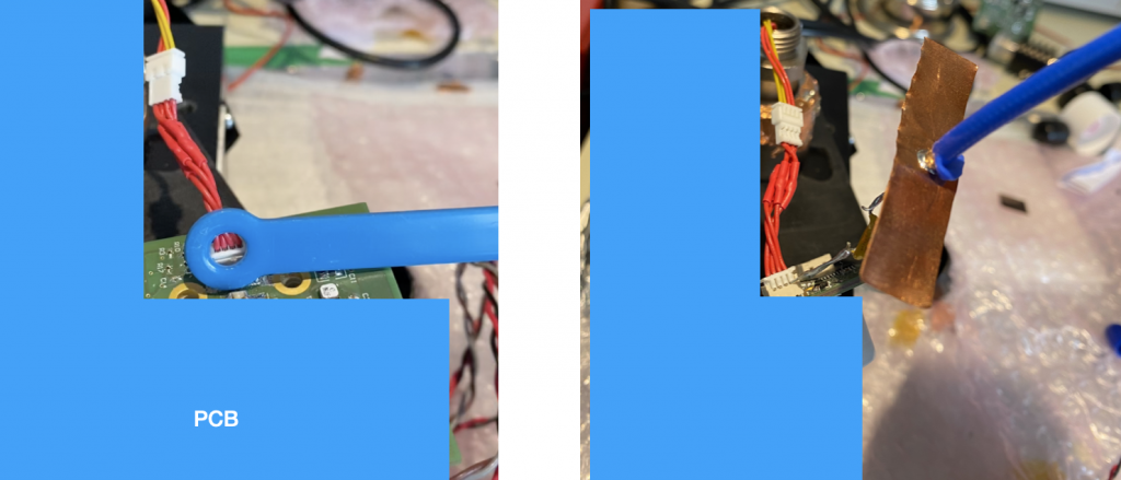
Under such circumstance, one should go back to the fundamental EMC diagnosis trouble-shooting process and apply the standard procedure. After using a workbench BCI test to re-produce the failure mode (see Figure 1), I started to use near-field probe and flying probe to inject local noise on the PCB and connection cable(see Figure 2). The weak point was quickly identified in this way. As many other projects, once the weak point/noise source is identified, fix only takes a couple of hours.
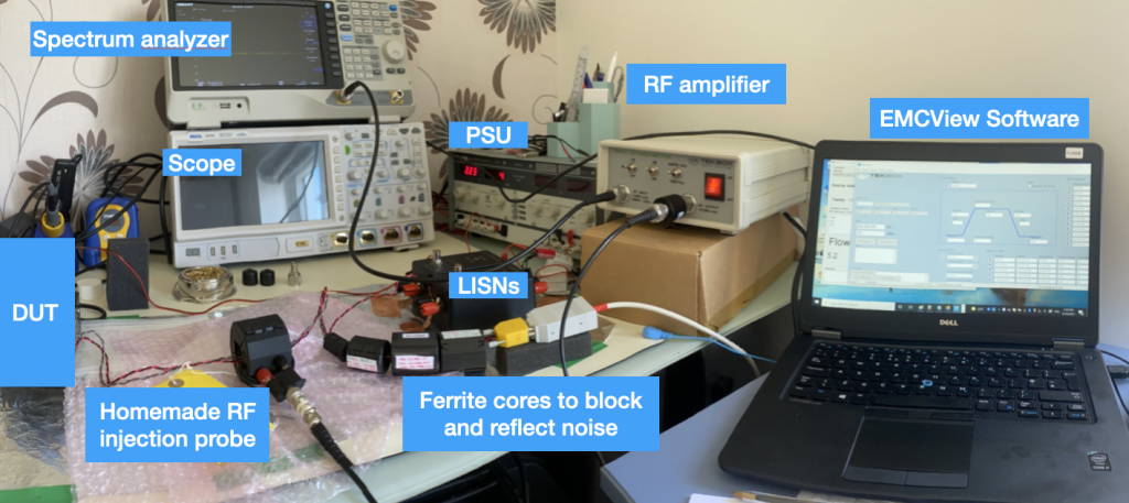
Note: we used ferrite cores that work in various frequency range between the BCI injection probe and the CAN communication kit. The ferrite cores in this case work in a way that attenuates the noise so that the CAN communication kit won’t be affected by the injected noise. The ferrite cores also reflect the wave so that more RF current is then injected to the DUT.