Project: Bulk Current Injection (BCI) failure in a remote control unit used in lorries
Timescale: 3 working days
Scope of work: To reproduce the BCI failure that the client’s customer saw in the BCI test. This work does not require fix, only to double check the result.
The client is a well-established European Tier-1 supplier.
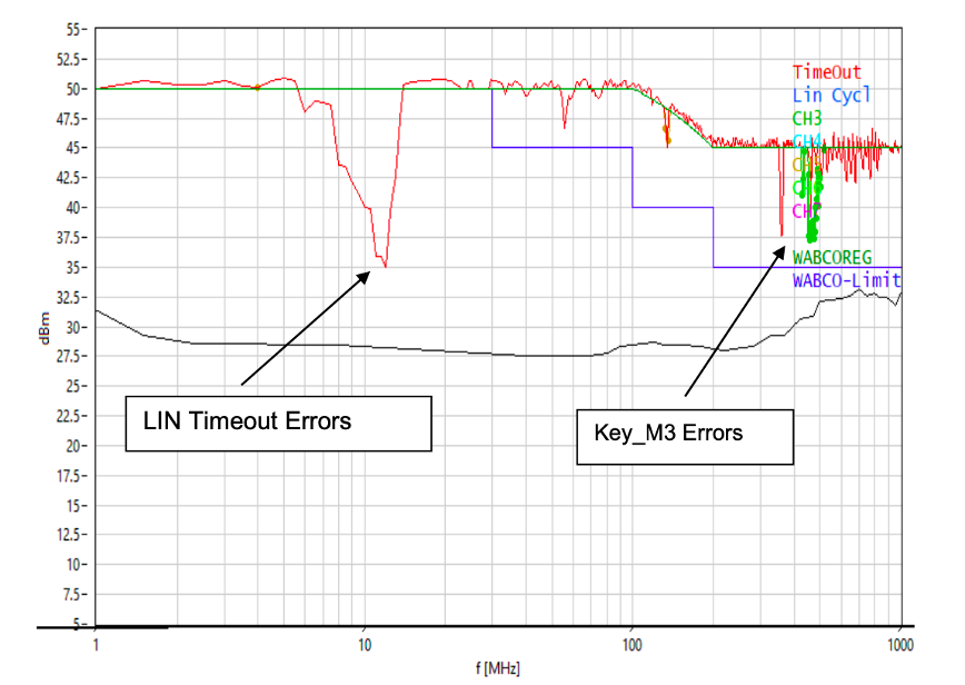
In this case, an automotive remote controller unit has experienced immunity issues during the BCI test in an accredited testing laboratory. The Local Interconnect Network (LIN) of the module lost communication in the frequency range between 5 and 15 MHz. The BCI test results is shown in Figure 1.
A diagram of the test setup is shown in Figure 2 and the test setup is shown in Figure 3. An RF current monitor probe was clamped to the cable to monitor the injected RF current level during the immunity test. Note that the current level depends on the output of the RF amplifier, the impedance of the capacitance value of the injection probe and the circuit impedance of the DUT.

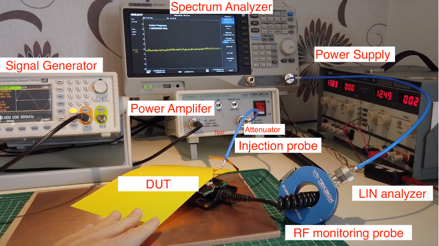
The test was simple to perform. One just needs to make sure that the RF amplifier input level limit not exceeded by supplying the right amount of reference signal. The signal generator was configured to do a fixed amplitude, variable frequency sweep between 5 and 15 MHz.
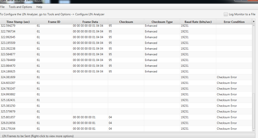
It was noticed that the LED lights of the DUT starts flashing during the sweep, the PC monitor also recorded multiple LIN communication errors shown in Figure 4. This was the same behaviour the DUT experienced in the BCI test. The current which was monitored through the RF monitor probe gives another useful tool to identify the potential issue on the circuit.