Project : In-situ EMC Pre-compliance Test for a nano-particle analyzer (Scientific & Laboratory Application)
Timescale : One working day
Scope of work: A laboratory equipment that is intended to be used in a lab environment. According to CISPR 11, this product should be classified as Group 1 (general purpose applications) and Class B.
The product shall be tested against:
EN 61000-3-3-2013+A1-2019
EN IEC 61000-3-2_2019+A1_2021
EN IEC 61326-1-2021
The client is a start-up medical/scientific/laboratory equipment manufacture.
The Product Under Test should easily pass EN61000-3-3 based on the following rationale:
- Both 12V and 24V power supply units used in the product are of high quality, and CE marked. Though we cannot trust these in general (unless detailed EMC performance report is provided by part manufacturers and reviewed by engineers who have good EMC experience), a visual check on the product gives good impression of their build quality.
- A good quality mains filter is fitted at the right location of the product and the earthing point is bonded firmly against the metal enclosure.
- Flicker is a problem for products that switch on/off high-power element (such as a heater). Products that generally need to worry about flicker are ovens, hair dryers, and some medical equipment. But for this product, there should not be any concern relating to flicker.
EN 61000-3-2 defines limits for harmonic current emissions.
The Product Under Test should pass EN 61000-3-2 based on the following rationale:
- Power supplies are of good quality (same as before).
- A good quality filter is fitted (same as before).
- The test can be tested in a lab where a current probe is clamped to the live wire, current is sampled and FFT analysis should tell whether the product passes/fail. But considering the load is less than 3Amp, chances of failing harmonic current emissions is very low.
EN 61326-1 defines the general EMC requirement, which includes immunity and emissions.
Our analysis is provided in the following table.
Table 1 Analysis of predicted performance of the product under test
| Test | Analysis | |
| ESD on Enclosure | IEC 61000-4-2 | Should be okay considering the build quality |
| Electromagnetic field | IEC 61000-4-3 | The only possible area that could be affected is the front panel screen, yet the risk is very low. |
| Power frequency magnetic field | IEC 61000-4-8 | This only affects things like electron beam related products or CRT. This product should be immune to low frequency magnetic field. |
| Burst on AC line | IEC 61000-4-4 | Filter should do the job |
| Surge | IEC 61000-4-5 | Filter should do the job |
| Conducted RF | IEC 61000-4-6 | Filter should do the job |
| Voltage dip | IEC 61000-4-11 | Filter and Power supply unit should do the job |
| Short interruptions | IEC 61000-4-11 | Filter and Power supply unit should do the job |
| I/O signal/ Control immunity | Make sure good quality cable, usb and ethernet connections are of good quality. When the connector needs to be bonded to the chassis frame, do so. | |
| Conducted and radiated emission | Defined in CISPR 11 | In-situ Test |
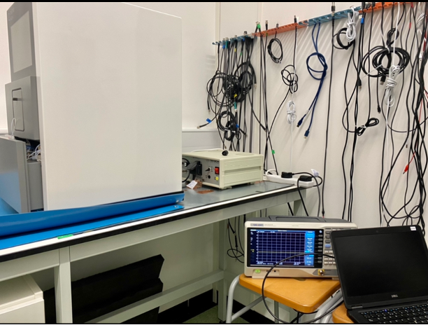
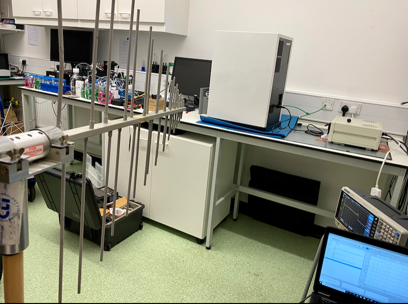
We carried out an in-situ conducted and radiated emission tests based on CISPR 11.
The test set-up is shown in Figure 1.
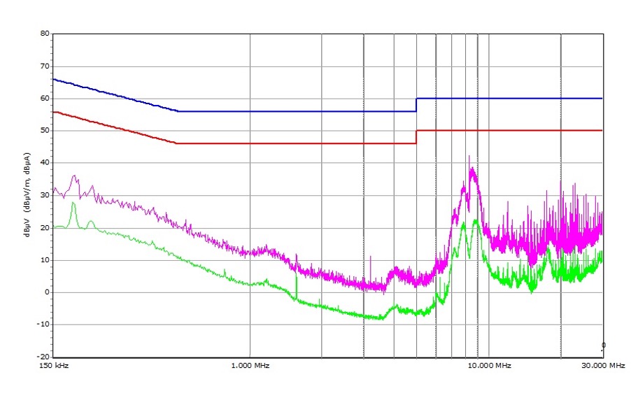
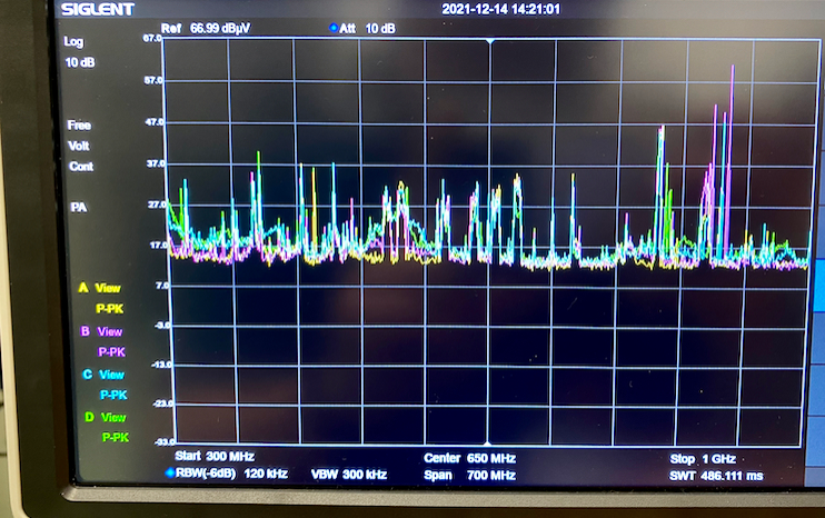
Both average and quasi-peak scan showed good performance of the unit. See Figure 2. Note the resonance is caused by the ambient, not the true performance of the unit. Even so, a 20dB margin means the product shall pass the conducted emission with confidence.
To test radiated emissions, one would need to set the test in anechoic chamber, and use 2-3 different antennas. The distance is set to be 3m between the product and the antenna. This cannot be achieved in the in-situ environment. Therefore, we did a 1-meter radiation test, only comparing the ambient noise and the noise when the unit is on.
A current probe method can effectively predict the radiation of mains cable up to 300 MHz. We did the current probe method first. Note that even with the ambient noise imposed on the cable, the predicted emission level is about 20dB lower than the limit.
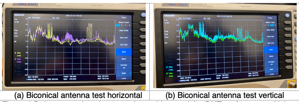
This is confirmed later by a biconical antenna set-up test (30MHz-300MHz).
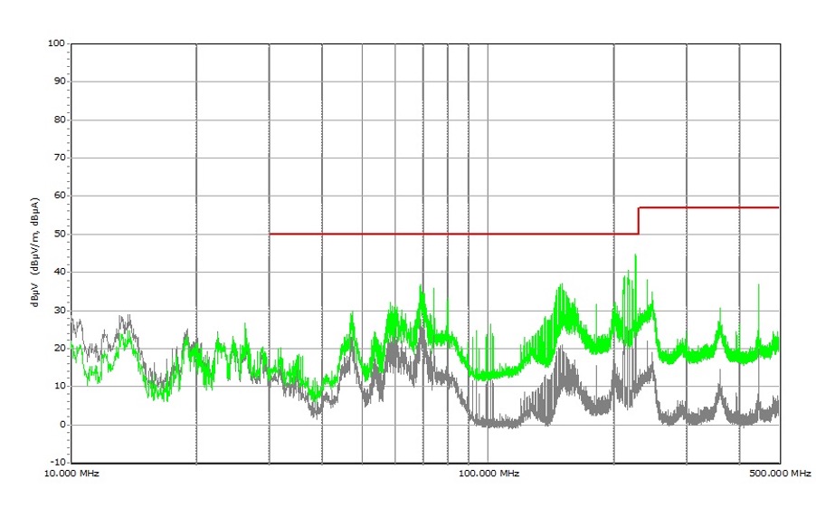
From 300MHz to 1 GHz, a log-periodic antenna is set up within a meter distance to check the radiated emission performance of the product.
Since the measurement is taken from 1 meter distance, we need to take the 3m limit and add 10dB to it to convert to 1 m test distance limits. The purpose is to indicate major “red flags’. There’s nothing major spotted during the test.
Near-Field Test
It was through discussion that we understood that the previous test was carried out using a near-field loop. Therefore, we also did a quick near field probe test. The findings are:
- Around the display, noise is the highest, close near-field probe caught about 37dBμV at about 100-200MHz range. This perhaps is not a big concern as, first, the noise level is not high, secondly, for this frequency range of noise to radiate efficiently, one will need a 30-60cm long cable structure connected to the display.
- A visual inspection spotted that the connector PCB to the display has two bonding holes which are not bonded to any metal structure at the minute, the advice therefore is given to bond this PCB to the nearest metal structure using either braid cable(short and thick) or wide copper. Another area that might radiate is the bundle of cables connected to the back of the display. If radiation does occur, suggest to put a ferrite sleeve of the cable bundle.