Project: A package of EMC work on a large electric vehicle
This is the part where we helped the client solve their onboard charger (OBC) issues.
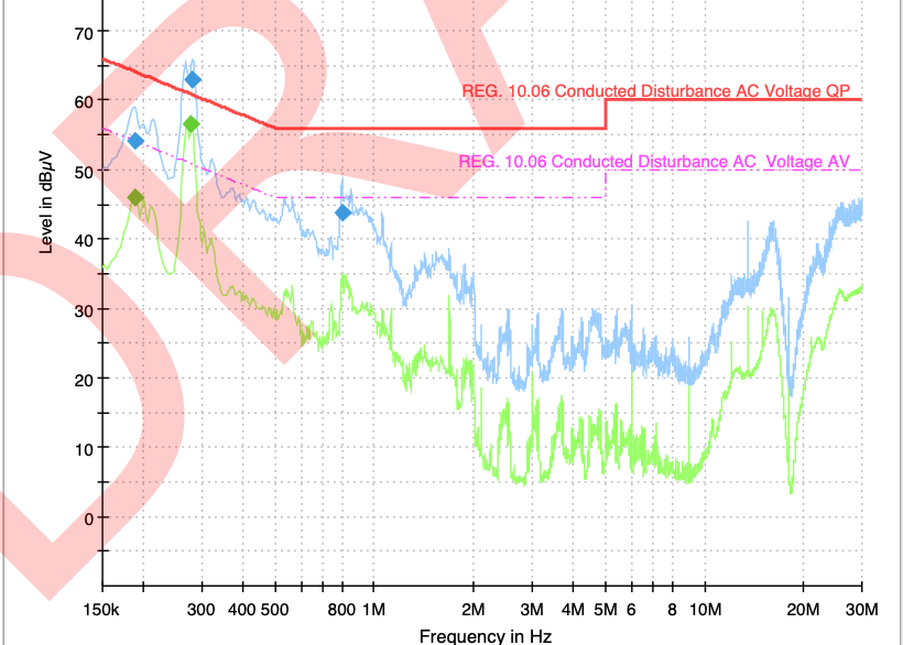
An on-board-charger (OBC) for EV applications failed the conducted emission tests during the vehicle level EMC charging tests. The failure frequency range is between 200 and 300 kHz as shown in Figure 1. Note that the Neutral wire result is shown in this case, but the profiles of other wires are almost the same as the neutral, suggesting the CM noise might be the dominant noise. It should be noted here that the OBC had passed the component level test with a good margin, the vehicle level failure indicates that the wiring and harnessing of the OBC might have contributed to the noise when it was mounted on the vehicle.
In this case, the investigation was performed in a vehicle test chamber where a three-phase LISN was available during the fault-finding stage. A current probe was clamped around L1, 2, 3 and Neutral wires to measure the CM current. Since a three-phase LISN was used in this test, one can calculate the LISN common mode voltage from the CM current; this is explained in Figure 2.
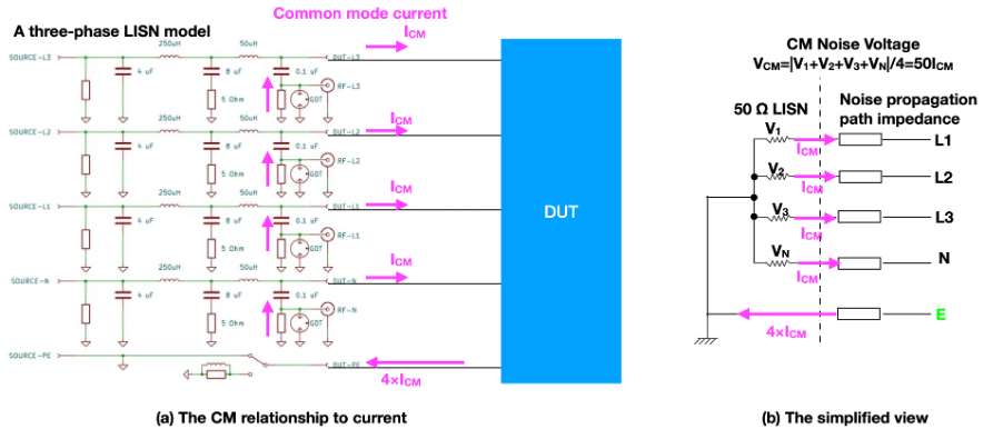
Figure 2 illustrates the CM noise voltages VCM, derived from the total noise voltage of each power line, V1, V2, V3 and VN. The CM voltage component is a quarter of the vector sum of V1, V2, V3 and VN. When a current probe is placed around L1,2,3 and the Neutral line, the total amount of CM current measured is 4×ICM, we can then derive the CM noise voltage as
VCM = 50 × ICM = 50 × Iprobe/4 = 12.5 × Iprobe
VCM(dBμV) = 22 + Iprobe (dBμA)
Where VCM is the common mode voltage measured by the LISN and Iprobe is the RF current probe reading in dBμA.
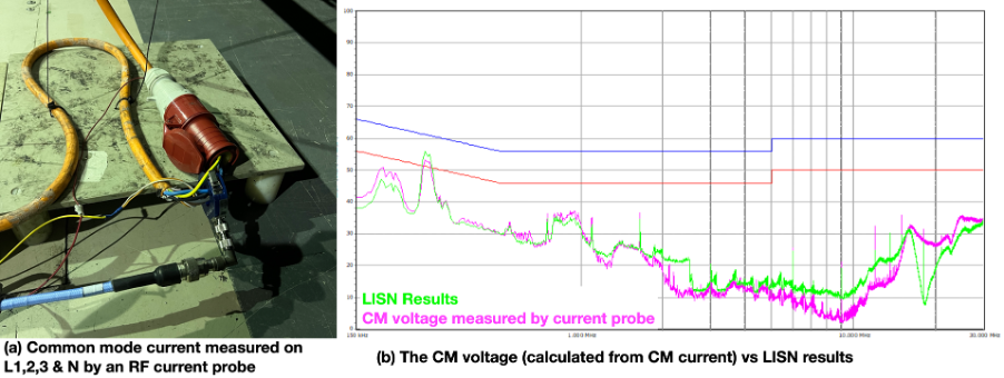
When factoring the 22 dB into the current measurement result, the CM voltage can be obtained; this result was then compared with the LISN measurement, as shown in Figure 3. The conducted noise is predominantly common mode in this case.
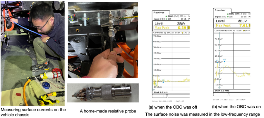
The fact that the conducted emission noise is common mode means that the earth wire of the OBC will carry a large amount of the CM noise. The earth wire of the OBC had a splice in this case, where one was connected to the EV charger, and the other was connected to the vehicle chassis. It was the chassis connection that caused the failure. To prove this, we measured the surface current on the chassis bracket where the earth wire was connected using a homemade resistive probe. It was shown in Figure 4 that when the OBC was operational, the low-frequency noise on the chassis was significantly high.
When we disconnected the earth wire from the chassis bracket, the conducted emission was reduced. Note that the earth wire was still earthed via the charging connection, so the safety aspect was not compromised.