Project : An HV switched reluctance motor drive used in automotive application
Timescale: 3 working days
Scope of work: The module experienced transient immunity issues in both the high voltage line and the low voltage line. Task is to fix the issue by enhancing the module’s immunity performance.
The client is an established American automotive Tier-1 supplier. This branch is based in the UK. Their client is a well established German OEM.
Challenge: HV transient means bulky filters are needed, but the module has literally no space to fit in an HV filter.
This project was challenging in a sense that we knew what should be done to enhance the immunity of the module, but we are limited with space.
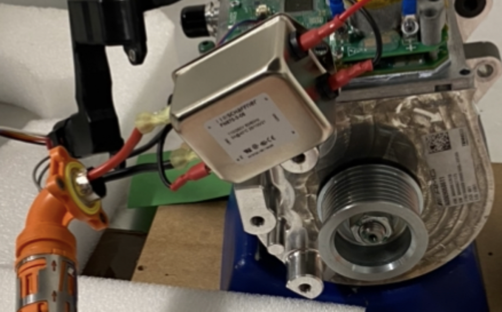
In order to save time and cost for the client, I used an off-the-shelf filter to prove the concept. The filter was not designed for the current rating of their product. But for the high voltage transient test, we were running the module in low power mode, so it was okay to use this off the shelf filter. Note that the transient test we tested was a voltage transient test (Burst C, similar to IEC61000-4-4 burst test). This is an important lesson, yes, we could always design a multi-stage filter by ourselves. But think about it, if you want to prove your assumption, it is much quicker and cheaper to buy an off-the-shelf part like this. If I were to build my own filter, it would have taken a few hours time and the client will have to pay for it. So in this case, it is really a no brainer to choose the off-the-shelf part.
Of course, we cannot showcase more information here due to the confidentiality reasons. But here I would like to share an interesting finding.
The DUT needs to be exposed to two burst tests, one is to test it against 5kHz with the other test to 100 kHz.
It was found that the DUT is susceptible to noise generated in the 5 kHz mode, but not the 100 kHz. Engineers were puzzled, because the pulse shape is exactly the same, by having a 100 kHz Burst, the energy injected into the system is a lot higher compared with that of a 5 kHz burst. So why the system is better coping with the transients at 100 kHz?
The answer is the DC link capacitors. In this case, the DC link capacitors are a few 220 μF electrolytic capacitors in parallel. Electrolytic capacitors (depending on types and manufacturers) often have a self resonant frequency at about 100 kHz. Some well-made electrolytic capacitors can have a much higher resonant frequency point. This means, the impedance of the capacitors is a lot higher at 5 kHz compared with 100 kHz. Checking the data sheet of the capacitors they use, the resonant frequency of the caps is indeed right at 100 kHz. This explains why the system has better immunity performance at 100 kHz.
This was documented in my article about DC link capacitors, which can be found here.