Fixing Radiated and Conducted Emissions in a Flywheel Power Regenerative System
Timescale: Total of 3 working days, plus additional review work
Scope of work: We were tasked with addressing both conducted and radiated emissions issues in a flywheel-based power generation system. The client sought a swift resolution due to project delivery pressures.
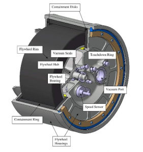
Storyline: Embracing clean energy has become an unstoppable trend, with the UK at the forefront of electrification efforts. Various technologies, including battery technology, fuel cells, and hydrogen, are undergoing research and development to achieve carbon emission goals. One intriguing technology in this landscape involves using flywheels for energy storage, delivering instantaneous power on demand.
Our client, a pioneer in this field with valuable intellectual property, faced a unique set of challenges. While the mechanical aspects of their technology were advanced, they encountered significant electromagnetic interference (EMI) issues. The bidirectional nature of power flow during generation and regeneration phases required bidirectional power converters to manage the process. These power converters, encompassing rectification and regenerative units, generated substantial EMI due to high-frequency switching of the IGBT modules and their relatively fast rise times. The significance of the rise time is emphasized in my article “Troubleshooting Low-Frequency Common-Mode Noise.”
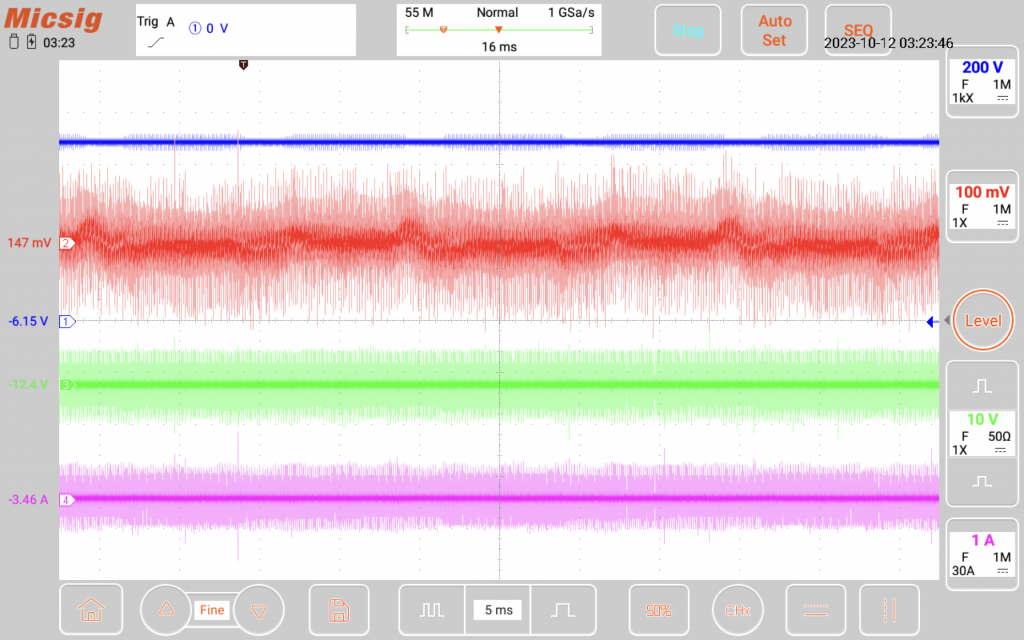
To illustrate the extent of the noise issue, refer to the image below, particularly channel X, which displays the peak-to-peak RF current on the DC bus bar between the rectifier and regenerative units. It’s important to note that this measurement was taken with a 20dB attenuator in place. Even with the attenuation, the calculated peak-to-peak common-mode current in this scenario reached an astonishing value of Xx Amperes—a startling figure. This explains why a ferrite core placed on the DC link quickly became extremely hot after only a minute of operation.
Consequently, it came as no surprise that this unit failed both conducted and radiated emissions tests. While we cannot disclose specific design details due to confidentiality, we can share valuable lessons from our experience.
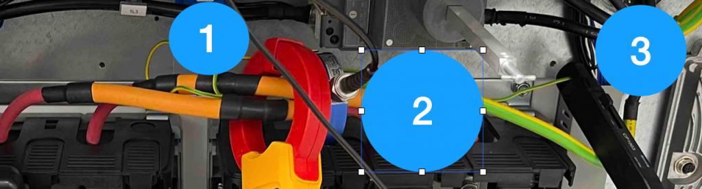
- In applications like these, grounding emerges as a pivotal consideration. Regrettably, in this particular design, the rectifier unit was not bonded to the same backplate as the regenerative unit. Consequently, the two “grounds” exhibited a significant voltage potential difference at radio frequencies, inevitably leading to increased emissions. How can this be proven? Simply use copper tape to establish multiple connections between the two backplates, and you’ll observe a reduction in radiated emissions.
- The design incorporated a low-frequency inductor, which ideally should have been placed in the same cabinet as the drive units. However, due to the client’s request, the inductor had to be positioned externally. This arrangement resulted in the presence of extra-long cables between the drive units and the inductor, extending for meters. It was anticipated that radiated emissions between 30 and 100 MHz would pose challenges. The solution once again hinged on effective grounding and shielding. Creating a robust common ground that allowed both the cabinets and the inductor to share the same plane proved instrumental.
- Addressing conducted emissions relied on the strategic placement of ferrite cores on the L1, L2, and L3 cable bundle, as well as ferrite cores on the earthing wire.
In the end, we managed to pass the EMC test with the unit—a significant relief given that certain design practices did not align with ideal EMC principles. However, as a company committed to meeting customer specifications, even when those requirements deviate from sound EMC design principles, we delivered on our client’s expectations.