Project : Solving a structure resonance issue on a fire alarm (Industrial Application)
Timescale : One working week
Scope of work: An audible and visual signalling device, which was designed to comply with EN54-3 fire alarm standard, experienced radiated immunity issues during the pre-compliance EMC test. The scope of the work therefore is defined as
1. To investigate the potential radiated immunity issue.
2. To carry out workbench pre-compliance test to reproduce failure modes.
3. To provide modification on the module, this often results in a delta in dB improvement to give sufficient margin to pass EMC test.
4. To document the project in a written format – report.
This project has spawned a publication, which is published with Signal Integrity Journal, titled as “Structure Resonances – ways to identify, locate and fix their associated EMI issues“. Below, some part of the article is subtracted from the article and put it here. For full-length article, visit https://www.signalintegrityjournal.com
Retrofitting a new IC to replace an older technology in an existing product often is not as easy as it sounds. Problems such as failing to function reliably or causing EMI issues could occur. Often such a fault is discovered after the original IC is no longer available in the market.
In the following example, a company is caught by surprise when they found a new IC daughter board they designed and mounted on the original IC pinout location has suffered from radiated immunity issues. Since the product is a sound product, tone issues were found when the unit was exposed to radiated emissions around 1.2GHz to 1.4GHz. The original IC is no longer available after more than 10 years of service time. The new IC is based on ARM architecture and is powered by 3.3V.
Identify the resonant structure
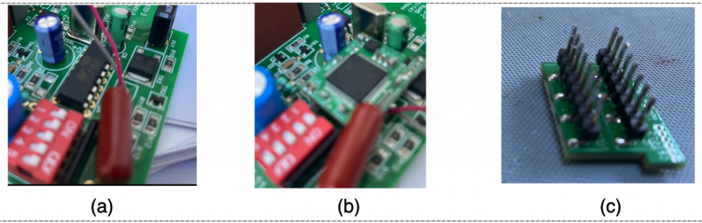
Both the original IC and the small daughter board that replaces the original IC are shown in Figure 1 (a) and (b), respectively. The backside of the daughter board shows that the pin legs are also bended 90 degree on the connection points, which inevitably introduces inductance in the connection between the two boards.
The daughterboard, with circa 374 mm2 area, 5 mm distance to the main board forms a capacitance of approximately 1 pF (based on simple equation C=ε0εRA/h). The long trace from the daughter board to the main board can easily have a 10nH inductance. The self-resonance of this board is then estimated to be 1.5GHz, indicating the system is more likely to have immunity issues at this frequency range.
Measurement
Among the techniques that could be used to measure the structure resonances, it has been found the method introduced in [1] is perhaps the easiest and cheapest set-up. A network analyzer or a spectrum analyzer with tracking generator can do the job. A directional coupler (a Mini-circuit ZFDC-20-5+ or ZFDC-10-5+) is needed to work with a spectrum analyzer whereas a network analyzer eliminates the need of a directional coupler since it can perform return loss. The basic idea is that a small loop radiates RF energy depends on its loop area, since the area in this case is small, it will only radiate efficiently above 3 GHz or so. Below this frequency, most of the RF energy bounces back due to reflection, the directional coupler directs some of the reflected energy so one expects to see a flat curve on the tracking generator result. Putting the loop close to a resonant structure, however, the RF energy could be absorbed by the resonance structure, causing a dip in the spectrum analyzer tracking generation plot results. A video demonstration by the author can be found in [2].
A shielded loop is supposed to perform better for this kind of test as it avoids capacitive coupling of the loop itself. But in reality, both shielded and non-shielded loop prove to work equally well most of the time.
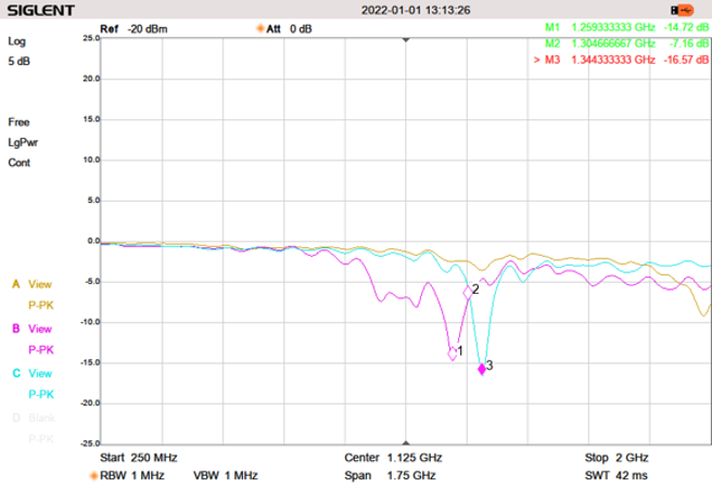
As one probes the field probe around the daughter board, dips in the tracking generator results can be seen in the frequency range that causes immunity issues (Figure 2).
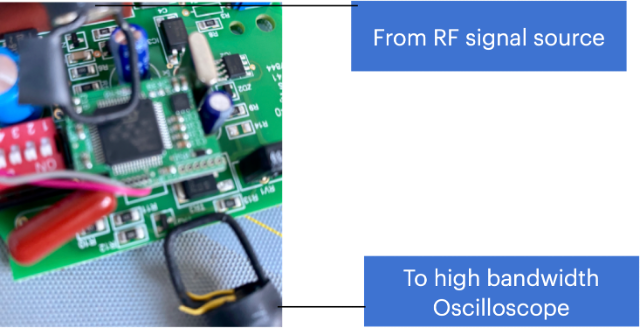
Alternatively, if a spectrum analyzer cannot be found in the lab. One can use a signal source (which is capable of producing the signals in the frequency range of interests, in this case, should cover frequency up to 2.1GHz) and a high bandwidth oscilloscope (at least 1GHz in this case), together with 2 square magnetic field loops. The set-up is shown in Figure 3, where one magnetic loop is used to generate noise across a wide frequency on the daughter board, the other magnetic loop is placed alongside the 0V trace on the mainboard. When the RF noise hits the resonant frequency, one can see a sudden jump in amplitude of signals measured in the oscilloscope. The jump in amplitude indicates at resonant frequency, the ‘ground bounce’ between the two boards becomes more obviously. The magnetic field loop basically picks up the noise via mutual inductive coupling between the trace and one side of the loop. One caution of using this method is that to be aware of the close field coupling between the two magnetic field probes.
Mitigation methods can be found in the article that the author published in Signal Integrity Journal.