Project: A 162.5 MHz noise spike used in an RF multimedia module cause radiated emission test failure
Timescale: One week
Scope of work: Since the module failed the radiated emission test at one frequency point, it needs to be fixed so the product can pass the CE test, emission test against EN55032.
The client is a multi-media device company specialised in broadcasting and video transmitting. It has US and UK offices.
Challenges: During the first few days of pre-compliance EMC test, the failure mode could not be captured.
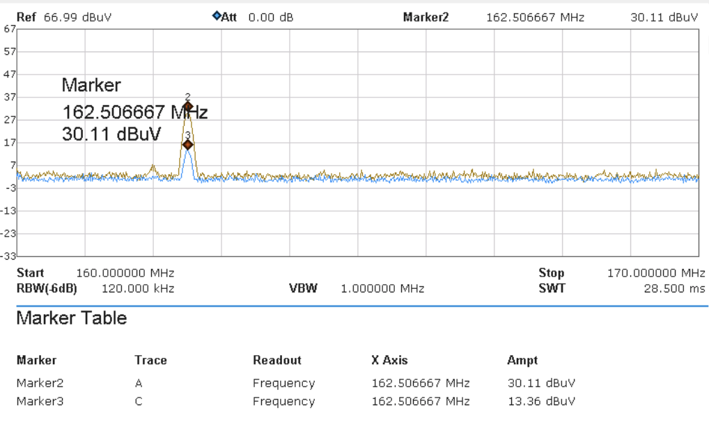
The Test result from test house is shown in Figure 1.
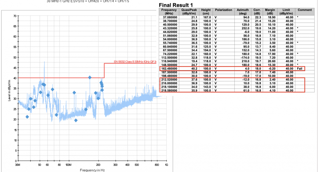
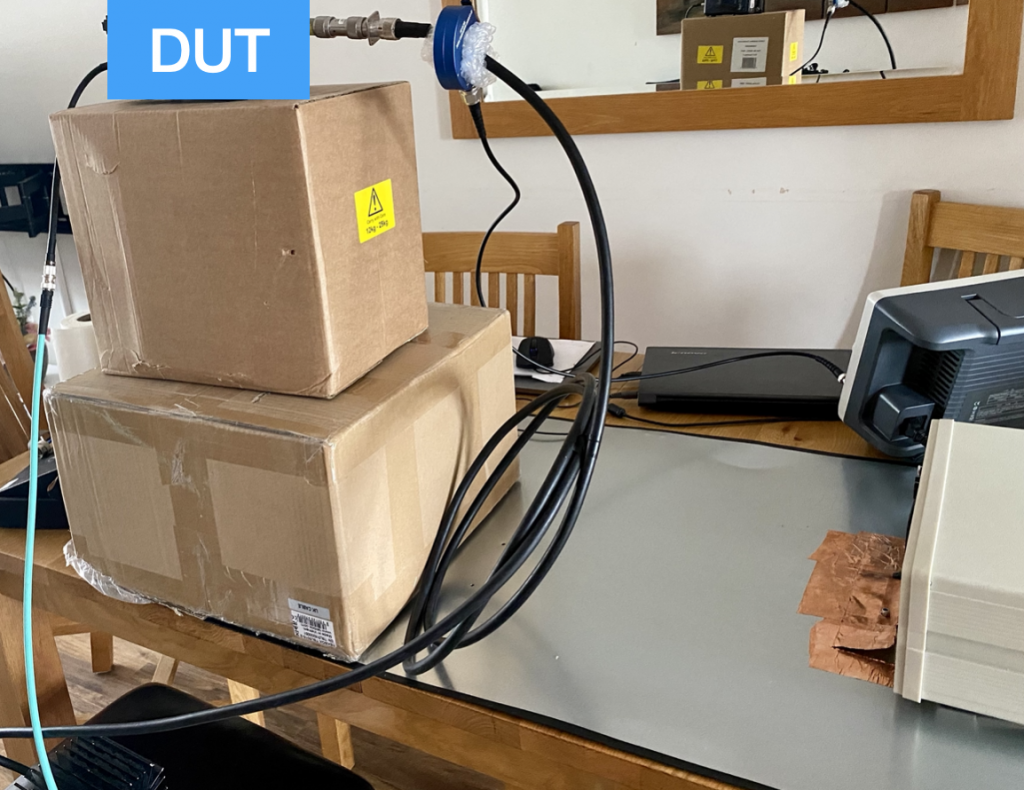
Since the failure mode was only at one frequency point (although in the range of 200 MHz, the margin was quite small), it was initially thought as an easy job. However, during the first few days, all pre-compliance test failed to capture the failure modes. Figure 2 showed the pre-compliance test set-up for this job. In this case, since the radiated failure was below 300 MHz, a current probe on the cable would capture suspicious common mode current. Most of the radiated emissions are radiated by the cables.
Even by using near field probe, the 162.5MHz noise spike cannot be captured, so what has been going on?
This is really part of the job, sometimes, a seemingly easy job could take a lot longer than expected. Often this is caused by intermittent noise signals which could not be easily reproduced. Bear in mind, many products’ performance depends on operating mode, temperature, etc. Though it is frustrating not to be able to capture the failure, one should always keep patient.
Then it was a thought, since the module was sent to the test lab without the client’s engineer being present, would there be a possibility that during the scan, the unit was accidentally reset without being noticed?
We quickly did a near field probe by restarting the unit, and the 162.5 MHz spike was successfully captured. It was also found that one side of the unit which had a WIFI module chip radiated most strongly.
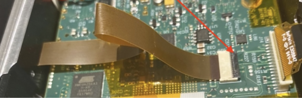
Once the noise source was identified, the rest was easy. After opening up the module, we quickly identified it was the ribbon cable inside the module which connects two chips (one of them was the WIFI chip) caused the problem. The ribbon cable was not shielded and it was unnecessarily long, which behaved as an efficient antenna. See Figure 3.
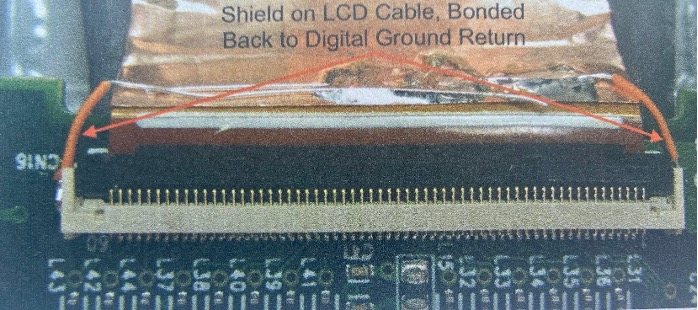
Ribbon cables are an EMC nightmare, especially when they lie all over traces and components and pick up stray capacitive noise currents from them. If they have to lie over traces and components, they should be shielded types (shields RF-bonded in the connectors at both ends) with overall insulation so they don’t short anything out when they touch it. Example given below
The fix therefore is to shorten the length of the ribbon cable and select a flat ferrite cable core so that the ribbon cable can be push through before it is connected. We can see an attenuation of more than 10dB at 162.5 MHz, which gives us great confidence that this modified module will pass the EMC test.
Lesson learnt: For intermittent noise source, one should test all modes, sometimes including a forced re-set, restart. EMC test generally only tests steady state operation, i.e. transient state such as start up and shut down are not tested. However, some chips, circuits might behave the same as start-up during certain running modes, which could potentially occur during EMC test. So it is always good to test these transient performance as well.