Project : EMC review for a luxury brand oven (Home Appliance Application)
Timescale: One working week
Scope of work: One of the pain points on the client’s other projects has been found late in the project that they were failing EMC requirements, which has resulted in redesign and a lot of testing, schedule changes, and it has been very expensive. The scope of this EMC consultant work, therefore, should be defined as:
1. To review the design of the product in development, this includes mechanical, electrical, as detailed as schematics and layout of subsystems.
2. Customer has test results, which indicates failures, together with item 1, weak points in the system should be identified.
3. To provide design recommendations so as to fix the issues, or prevent the product from failing EMC test.
4. To educate the design engineers of good EMC practice, this should be well documented in a written format.
Recommendations: Here are some of the recommendations (selected from the final report) we provided to our clients.
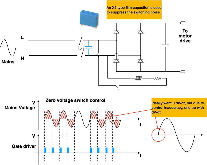
High power element switched in a PWM fashion causes large di/dt and dV/dt interference. Two types of high power element switching are available, AC switching and DC switching. AC switching turns on and off mains voltage directly while DC switching switches at the rectified DC level. Common AC switching devices are TRIAC or thyristor. Common DC switches are MOSFET or IGBT. AC switching is more popular from both size and cost point of view as DC switching means more expensive devices and higher rating rectifiers.
There are two types of AC switching methods, namely mains zero cross switching and phase angle switching. Mains zero cross switching method only allows switching actions to take place at exactly the point where the AC voltage crosses zero (Figure 1). The benefit of this method is it avoids high dV/dt associated with the conducted noise emission. However, due to the propagation delay between the microcontroller and the device gate drive, true zero cross cannot be achieved. While the delay can be compensated in the software, the turn on delay of the switching device itself cannot be compensated as it depends on the fabrication of semiconductor devices. Because the delay is quite minimum, an X2 type film capacitor along the mains line is often sufficient to suppress the noise (as the noise is predominantly differential mode in this case).
One method to avoid the propagation delay is to add software compensation, this can be achieved with minimum hardware change since it is a software implementation. However, test needs to be set up to first measure the delay, the test also needs to be repeated across a few samples to make sure that the delay is consistent and sits in a time window. According to our experience, the window could be between hundreds of nanoseconds to hundreds of microseconds). Software compensation basically means firing the TRIAC slightly earlier. This is often achieved by software predicting the next zero cross point.
Note: An X2 type capacitor in this kind of application also deserves attention to details because the capacitance value of an X capacitor can be reduced significantly over years of service. This is particularly true if the capacitor is used in a humid environment. I have seen cases where an X capacitor’s capacitance value dropped to only a few percentages of its rated value in a year or two.
What has been happening is that damp air can leak into the capacitor, up the wires, and between the box and the epoxy potting compound. The aluminium metallization can then oxidize. Aluminium oxide is a good electrical insulator, thereby reducing the capacitance. That’s one problem all film capacitors can have. The problem I was talking about was the film thickness. Reputable capacitor brands use a thicker film, resulting in a larger capacitor than other brands. The thinner film makes the capacitor less robust to overload (voltage, current, or temperature) and less likely to self-heal as well.
For details, see https://incompliancemag.com/article/capacitors-theory-and-application/
Stacked PCBs with wire connections
The control board and power board are stacked together with wire connections as shown in Figure 8. This configuration may have a problem as the structure (2 PCBs form a capacitance in between, the wire connection serve as an inductance) could become an L-C tank circuit. So chances of this structure radiating/being susceptible to radiated noise are high. At this stage, perhaps we should just note this down since resonance issue cannot be easily studied without performing a bench test.
Should emission/immunity issues occur due to the structure resonance, mitigation methods need to be put in place. These mitigation methods include putting ferrite sleeve on the connection wires, or insert EMI absorb sheet between the two PCBs. We have many years of experience solving structure resonance issues using cost-effective solutions.
General advice on mains filters
The success of this product passing EMC standards depends on wiring harnessing inside the cabinet and the effectiveness of the filter design. Since the filter is located on the control board, layout on the PCB is important. Of course, wiring is also important as we explained.
The best practice is to locate the AC mains filter at the entry point of the product, this is easier said than done considering the design constraints of this particular product.
If more mains filtering is needed, then consider the following option as a cost-effective solution.
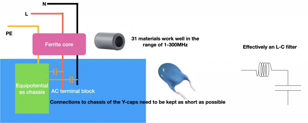
Y-capacitors can be served as good common-mode low-impedance path for noise in general. However, the Y-capacitance value needs to be selected carefully considering the leakage current requirement for this product. The best location for Y-caps in this product is the mains terminal block, which is close to the entry point. When using Y-caps, make sure the leads of the Y-caps are kept as short as possible. Also, Y-caps work the best with high-impedance on the line. Challenges here is that the high current rating means any magnetic component would be costly, heavy and bulky. However, one still can use a ferrite sleeve (with the right size of diameter) to act as a common-mode high-impedance path for the noise. Together with the Y-caps, this should serve a cost-effective filter solution. Since the ferrite core is used here as a common-mode filter, the core cannot be saturated because the differential low frequency current sum is zero.
See illustrations below: