Project : Investigating an EFT/Burst Immunity issue on an X-ray medical equipment (Medical Application)
Timescale : One working day
Scope of work: A 3D X-ray system, designed for VET application has experienced some EMI issues in the pre-compliance EMC testing stage, the scope of the package of work therefore are:
1. To investigate the potential EMI issues
2. To carry out workbench pre-compliance test to reproduce failure modes.
3. To provide modification on the module, this often results in a delta in dB improvement to give sufficient margin to pass EMC test.
4. To document the project in a written format – report.
The client is a small to medium size company specialised in making X-ray related medical equipment.
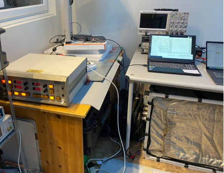
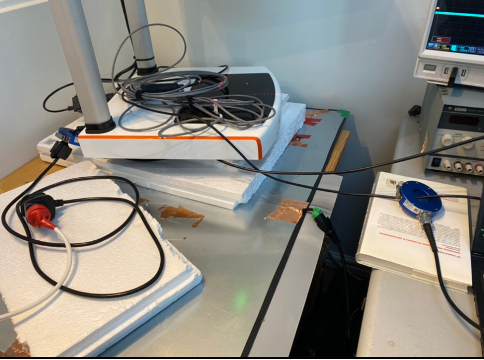
The equipment under test (EUT) was placed on 100mm insulation support which sits on a ground plane. The electric fast transient (EFT) generator was configured to apply 100kHz, 2kV burst pulses via its internal coupling and decoupling network (CDN) to the EUT. The set-up is shown in Figure 1.
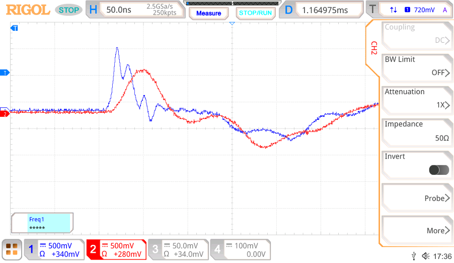
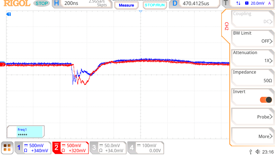
A pair of matched RF current probes (Bandwidth to 600MHz) were placed on the mains cable and the USB cable, so that the high frequency RF noise can be monitored during the test. Note, because of the high energy in these pulses, each probe is connected to a 30dB attenuator before they are plugged to the 50Ω (rather than the 1MΩ) input of the oscilloscope. This, inevitably, affects the shape of the current waveform. But for comparison study, this is good enough.
From the results, it is clear that there’s a strong coupling between the USB link and the mains cable. The current on the USB link was not far off from the level as what was measured on the mains cable.
During the test, it was observed that:
- The RF noise level on the cables (both mains and USB) showed higher level when the burst pulses were applied to the PE port.
- The EUT was more sensitive to negative EFT pulses.
A brief overview of the product layout showed the following parts need to be assessed.
- The PE lead is unnecessarily long, which means that during the high frequency RF disturbance, a large voltage will be developed, this could pose a problem.
- The shield that is wrapped around the Würth USB stick might have a detrimental effect rather than improving the product EMC performance.
The general layout of the system inside the enclosure needs to be carefully designed to improve its EMC performance.
Temporary fixes using ferrite cores
Though it is not a preferred approach, ferrite cores were tried on various locations of the EUT to minimize the impact of EFT pulses.
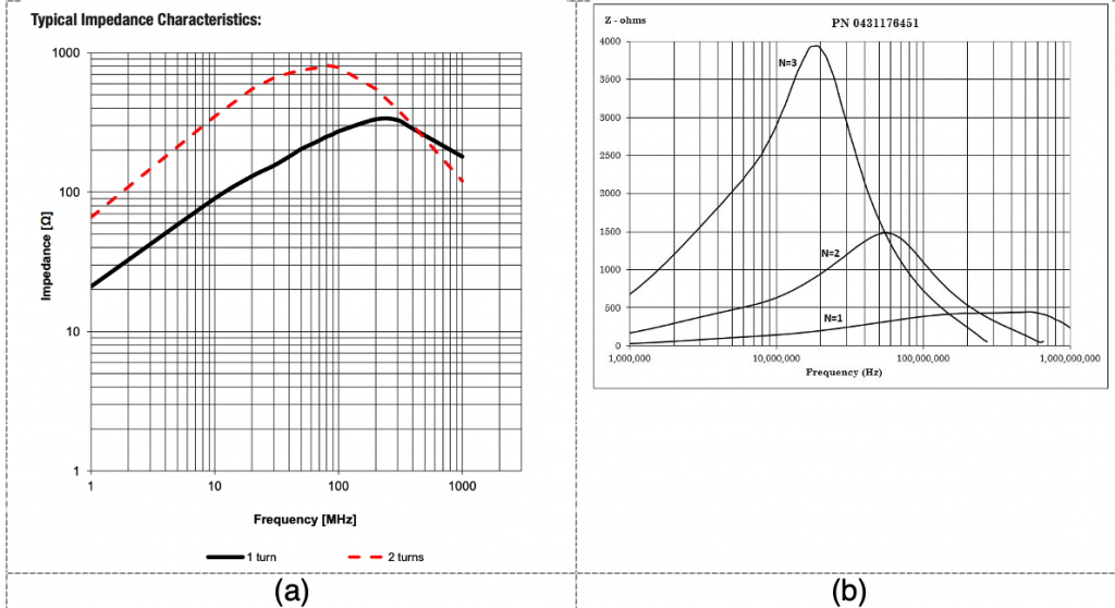
It was found that the current ferrite core (Würth 742-717-22) is not effective in blocking the EFT noise. We were aware of the fact that this core was used to suppress emission issues. A different choice of ferrite core (Fair-rite 0431176451) with the same configuration, i.e. 2 turn on the mains lead demonstrated a much better attenuation of the EFT pulses, as shown in Figure 4.
Cross checking the impedance curve of both parts (as shown in Figure 5), we believed that the fair-rite part is a better choice. It will not worsen the conducted/radiated emission profile of the EUT, in fact, it should make the emission performance much better.
EFT immunity basics
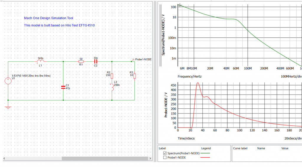
Suitable ferrite cores need to be selected for the EFT as the burst pulses have very different frequency spectrum due to its sharp rise (5ns) and slow fall (50ns). A simulation model gives a good indication at which frequency we need to suppress the noise. See below, it is thus easy to say a 31 material is a good choice for this.