Project: A battery powered inverter module used as an off-the-grid power supply unit (Industrial Application)
Timescale: Two day site visit (Test In-situ) + 2 day review
Scope of work: Identify noise source which causes the module failure in conducted emission test, fix the issue so the product can pass the EMC limit. Review work to help next generation design to avoid the same failure from happening again.
The client is a small to medium size enterprise (SME) based in the UK. The module is a relatively large size cabinet. The EMC test standard are 61000-6-4 Class A.
Challenges: complex wiring system within the cabinet, large current means magnetic component section is limited.
The module conducted emission test result is shown in Figure 1.
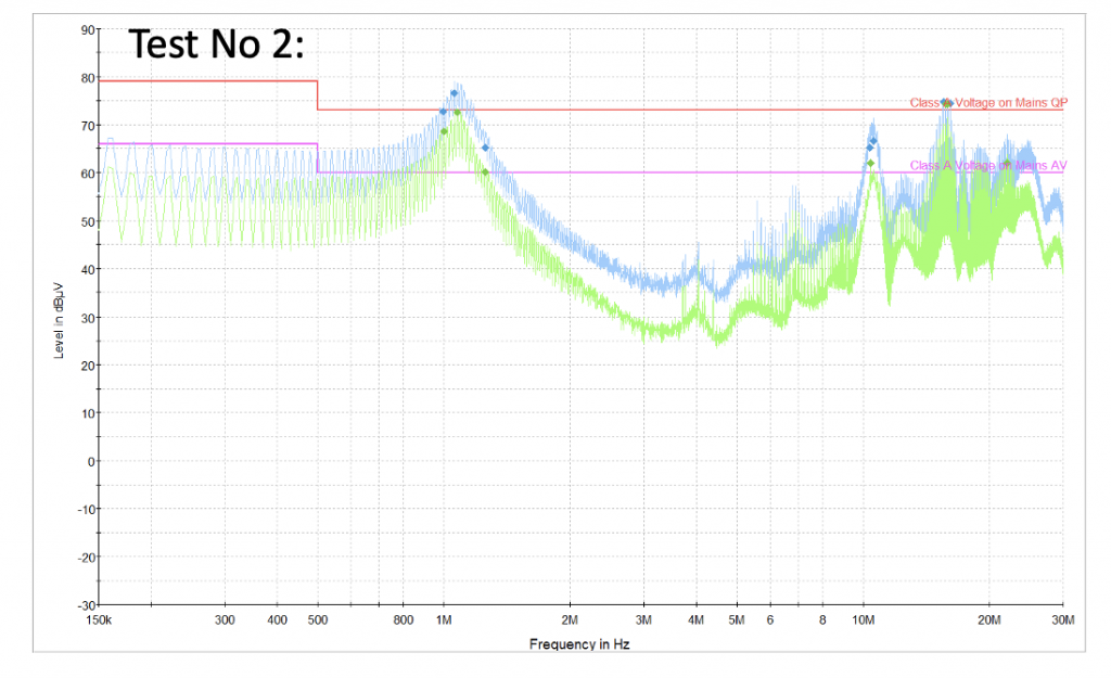
Figure 2 shows I was on site for trouble-shooting.

Identify the noise source:
For a system like this, often the noise source comes from more than one places. Though it is true that we could spend time identifying each noise source, the time often doesn’t allow us to do so. In order to get down to the bottom of the problem quickly, here we need a different approach.
Coupling:
Again, the wiring and harnessing inside the module is very complex, it is going to take a lot of time to understand which path causes the coupling. It is interesting to note that in this case, not only the power cables couple the noise, so do the communication and signal cables. After all, energy travels in space not inside the cable, so any conductor can couple noise.
Fix:
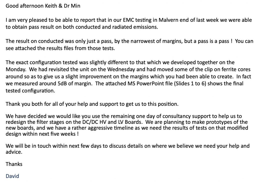
For a product like this, the most efficient way is to apply an efficient filter. The filter is most effective at the connector (entry or output) point of the module (not inside the module since the filter can be bypassed by nearby cables). In this case, after a few modifications on the filter, the module passes the EMC, see client’s feedback email shown in Figure 3.
Review work:
The following review work revealed many areas of Improvement in their design. Of course, for confidential reasons, we cannot share the information. However, we list two issues here to share.
First is TO-247 package MOSFETs were used as the devices of choice, clearly the choice was made from thermal design and BOM cost point of view without EMC design consideration. TO-247 devices are cheap, not they are not good packages. The long lead of the device could easily introduce 10nH parasitic inductance, together with the parasitic capacitance of the device mounting, when energised by a fast switch, a ringing and overshoot could easy occur, which was the case. This ringing caused large common mode noise measured on the input side cable.
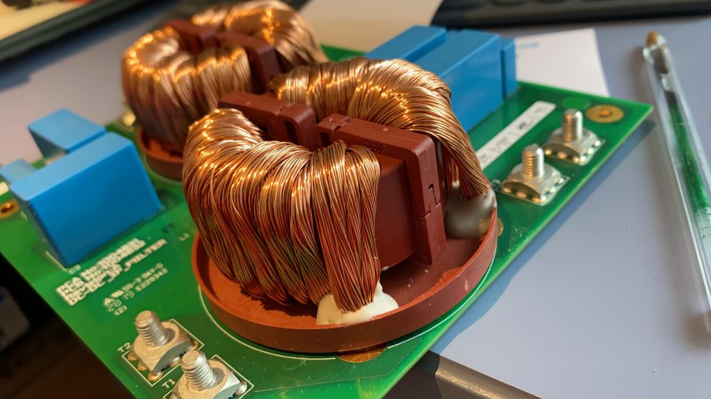
On the LV side of the converter, two common mode chokes were used. These two cost lots of money, takes space and they are heavy. Because of the current rating is above 50Amp, it is extremely difficult to find a suitable inductor/common mode choke. But the CMC of choice hasn’t done any good attenuation for the common mode noise. Reason? The structure is a rope type winding, introducing a fair amount of interwinding capacitance, for low frequency noise, this is okay, but not for noisy signals above 10 MHz. This point was proved by the fact that when removing the CMCs, the noise profile between the 20 and 30 MHz range did not change, however the 150 kHz range performance got worse. The big CMC used for input filters is shown in Figure 4.
Lessons learnt:
Try not to use TO-247 package if you can, even though the BOM cost might look higher with the surface mounted types. But by good device selection and layout, you could potentially eliminate the need of heavy filter such as those shown in Figure 4. Think again, would you still choose TO-247 device?
CMC needs to be carefully selected as often their performance can be compromised, in this case, the common mode attenuation performance were compromised, however, as we saw, when removing the CMC, the low frequency differential mode performance got worse, indicating that the CMC’s leakage inductance actually helps reducing the common mode noise.