Project : An HV junction box used in a battery pack (Hybrid Vehicle Application)
Timescale : One working week
Scope of work: Identify the noise source which causes the conducted & radiated failures in EMC test and apply production ready fix.
The client is an established Japanese automotive Tier-1 supplier, their customer is an established automotive OEM based in the UK. The module which failed the test is a high voltage battery junction box used in a HV battery pack. The module failed both conducted and radiated emissions, especially at the FM band (where the OEM care the most).
Challenges: The tight timescale, limited space given in the product, fix needs to pass environmental test as well.
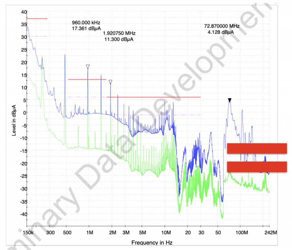
Automotive EMC test is one of the most stringent EMC test limits. In this case, the module is tested against CISPR 25 Class 5 equivalent. The failures in the conducted emission test can be seen in Figure1.
Identify Noise Source:
Just through paper review, in which we reviewed the design, the schematics, the layout and the CAD. We identified the noise source is actually a small DC-DC module used in the current sensor. The current sensor is also from a global company, which passed industrial EMC standard but not the automotive one. To make things worse, in this case, the CAN bus frequency happened to double the frequency of the switching frequency of the DC-DC. Hence the true noise source had been hiding for a while.
Identify Noise Coupling:
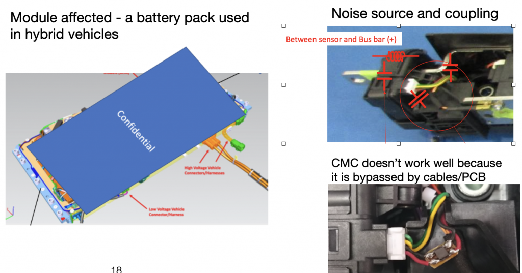
Since the current sensor is mounted on the HV DC bus bar, it has a strong magnetic and electric coupling to the cables nearby. Once the noise started propagating in the system, it was everywhere, so it was picked during the battery pack EMC testing.
The noise source – the current sensor and how it is coupled to its nearby circuits is shown in Figure 2. The CMC didn’t work because the CAN bus cables bypassed it.
The Fix:
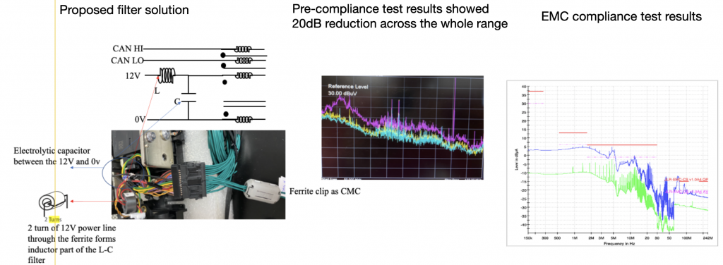
It is important to design a proper filter to suppress the noise, in this case, a two-stage filter was built in house to reduce the noise. As it can be seen from Figure 3, 20 dB reduction was achieved across the whole frequency range, indicating the effectiveness of the filter.
Finally, it is important to finalise the filter design so that all the components can be fit into a small size PCB. For automotive application, the filter PCB shall also pass vibration tests.
Lesson Learnt:
Never underestimate a seemingly harmless unit, in this case, a small current sensor causes a big problem. When applying common mode choke, often the effectiveness is compromised, one should always know where and how to apply filters effectively.