Project: Review, Testing & Troubleshooting of an Automotive Power Distribution Unit
Time scale: 4 working days
Scope of work:
The device being tested (referred to as the DUT) serves as a power distribution module intended for use in automotive applications. Key attributes of this DUT encompass semiconductor switches, onboard I2C and modified SPI communication protocols, as well as external CAN/LIN communication capabilities.
Upon initial evaluation, it was evident that EMC considerations were taken into account during the design process. The main PCB is composed of a 12-layer stack-up and features a dedicated ground plane formed by a copper flood. Signal pathways have been strategically routed orthogonally between different layers. Notably, high-speed signal lines have been equipped with series terminating resistors in designated positions. The design also incorporates specialized filters for power supplies, which have demonstrated effectiveness based on previous experiences.
As part of our proposed approach, we outline the following tasks:
- Schematic and Layout Review: We will conduct a comprehensive review of the design’s schematics and layout, aiming to ensure alignment with EMC considerations.
- EMC Requirement Analysis: We will delve into the EMC requirements stipulated by Volvo (STD 515-0003, May 2023), performing both an EMC risk analysis and a gap analysis to identify potential areas for improvement or adjustments.
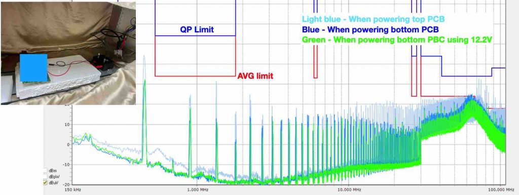
- Benchtop Pre-Compliance EMC Testing: This phase involves conducting preliminary EMC tests on early unit samples in a controlled benchtop environment. The focus will be on critical tests, including conducted emissions, radiated emissions, conducted immunity, and electrostatic discharge (ESD) tests.
Through these activities, we aim to strengthen the DUT’s EMC performance, ensuring compliance with Volvo’s standards and enhancing its overall reliability for automotive applications.
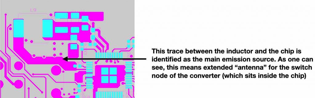
Work Progress: During the conducted emission test, we noticed that the unit failed the Volvo automotive test standard in the FM band. Despite the design being well-regarded, troubleshooting the noise source and coupling mechanism proved challenging. After hours of work, we successfully identified that the noise was contributed by a synchronous converter chip. When routing the trace between the chip and the inductor, the long copper trace became the main noise source. The solution was to re-design the board to address this issue before the next design stage.